Mixing Hobbies and Code - Part Two
June 24, 2019
Last post I explained my fear of burning out as a developer and the fear of ruining even my hobbies by folding in dev work as side projects. In this post we pick up (with excitement) the hardware necessary for the project I settled on.
The Parts - A list
- (2) BBC Micro:bit microcontrollers
- (2) AAA battery holders with jst male connectors
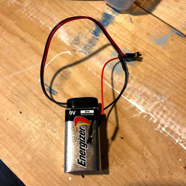
- (1) 9v battery holder
- (3) spst micro switches
- (1) mini breadboard
- (1) SN754410 dual h-bridge IC
I got most of this through adafruit, though I did get the h-bridge ic through mouser electronics.
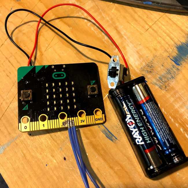
The Controller
The micro:bit already has a jst connector built in, so taking one of the AAA battery holders (one that came with my engine kit had a spst on/off built in) clip a space in the hot wire and solder in the on/off. At the end of the wires, I added a jst male connector. Plug this into the Micro:bit and we're done!
Preparing the 9v
This is a lot like the controller. Splice and solder in a tiny spst switch, but this time I added little pins to connect to the breadboard.
Preparing the Other Micro:bit
First we need to repeat the on/off and jst step from the controller. Then I needed two (though you'll see three...) wires attached to pin 13 and pin 14 on the Micro:bit's pinout. This is a bit frustrating because the contact for 13 and 14 are pretty narrow and close together. It was a little fiddly, but they can be soldered. At the ends of each of the wires I soldered a pin to connect to the breadboard.
The H-Bridge IC
The pinout for the chip goes around counterclockwise from the litle notch at the top: take a look at TI's docs
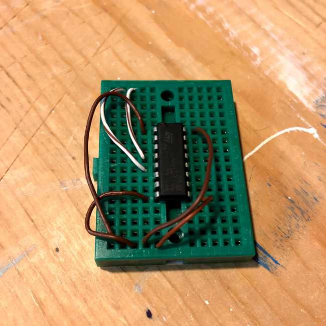
With the IC on the mini breadboard I could plug a few of the wires:
- Pin 1 (top left) gets 9v which enables the motor pins on the left side.
- Pin 8 (bottom left) gets 9v for motor power.
- Pin 16 (top right) get 9v for the chip.
- Pin 4 and 5 are grounds.
- Pin 3 and 6 connect to the motor.
- Pin 2 and 7 will connect to the wires I soldered to the micro:bit.
- Pin 9 enables the motor control on the right side. I'm pretty sure I didn't need to do that one...
Mashing it All Together.
I put the breadboard in first then arrayed 9v, the Micro:bit, and it's AA batteries into the cab.
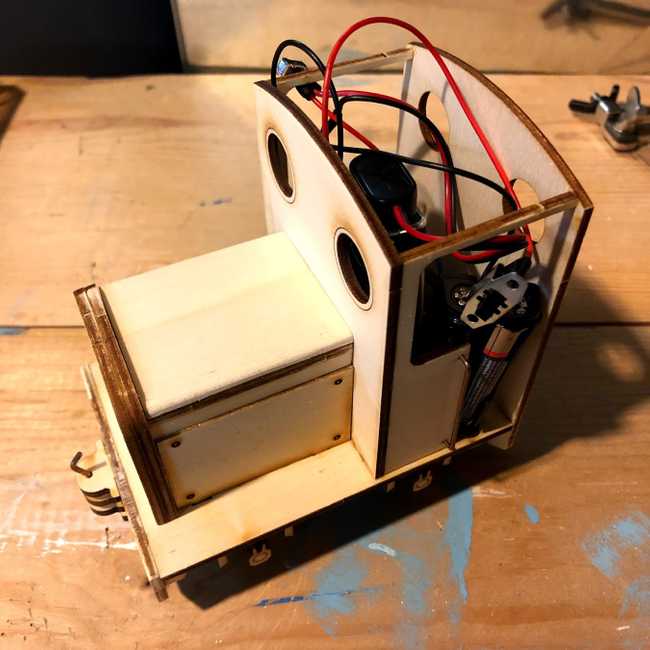
With that, the hardware is ready to roll. Next post will cover the code to make the bits control the engine and talk to each other.